Monday, March 8, 2010

Input/Output

This weekend was an exercise in what must be a successive approximation of ISO9000 compliance for PCB assembly. I went down to Adafruit Industries and my hostess provided me with: a MetCal; a fume extractor; a pair of diagonal cutters and a bit of her invaluable time over a 36-hour window. With these ingredients, I magically transformed a 65# suitcase of components into 20 laboratory EKG amplifiers. Then I used her laser cutter to mark (for drilling) and label all of the enclosures. It was one hell of a transfer function.
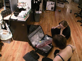


Fig 1. The Input  
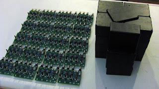

Fig 2. The Output

Between this and the 2009 Ninja Networks Party DefCon Badge assembly extravaganza, I'm overdue in giving a breakdown of how to bring medium and large-scale PCB assembly into the reach of a DIY-crew with enough time, enthusiasm and lack of OSHA oversight*. There are tons of things you can do in your home (but preferably in some borrowed industrial workspace) to assemble your own production-quality PCBs for low overhead -- and there's absolutely nothing mystical about how 90% of electronics are made. All the nebulous magic is reserved for how to make staggering volumes of things cheaply, quickly and reliably -- a process which Bunny has already demystified.


*OSHA really doesn't like it when you drink beer at your bench.

Wednesday, February 10, 2010

Emission Spectra

The New Year brings in good things!

When I was learning how to knit, I spent a long time trying to cajole a friend of mine into making me the world's geekiest present: an emission spectrum scarf. It didn't pan out, but over New Years (and over drinks) we were circulating the idea around again and now it looks like Stern Lab is on assignment!

Becky over at Stern Lab is making emission spectrum scarves! Once she starts selling them at her Etsy store, you should go pick one up! Best. Present. Ever.


Fig 1. Silicon

Monochron

Every Christmas break is another opportunity to go down to Adafruit Industries in NY, NY and (in addition to having a good time) exercise my nascent industrial design impulses. The new tradition is to knock out a kit enclosure. Adafruit's design constraints were as follows:

1. The enclosure needed to be made out of 1/8" acrylic.

2. It would preferably be completely enclosed.
3. She didn't want "just a box."
4. It should have a variable tilt angle to accommodate the viewing angle of the LCD screen.

Until I get a copy of my notes back (which show my entire thought process, including doodles and the Bad Ideas Club) - these photos will have to suffice. I designed everything to slot together because I really like slotted flat-designs (go read Nomadic Furniture 1 & Nomadic Furniture 2 for more fun flat designs and examples of things Frank Gehry was actually good at designing -- PROTIP: It's not buildings)!


Fig 1. Notes 1


Fig 2. Notes 2


Fig 3. Notes 3


Fig 4. My draft enclosure in clear acrylic.

There were a couple of things about my prototype that I knew Adafruit didn't like. I had an asymmetric profile shape - chosen because I based the design off of an isosceles triangle, and a truncated triangular side profile meant I could slot the top piece in for ultimate interlocking action. I also really enjoyed the idea of having a low, flat very Byzantine/monolithic/robots-will-eat-you shape, which made the enclosure larger
than Adafruit's prefs. She ended up removing the top and changing it out to match the tab-locking bottom piece, while retaining the slot-locking sides and front piece, which allowed her to shrink the front piece down and make the area surrounding the LCD symmetric. The final case retains a lot of the details I enjoyed making while matching Adafruit's own preferences. The following pictures show what the final production design will look like.


Fig 5. Back in Black


Fig 6. Symmetric Side Profile


Fig 7. Rear View

Wednesday, February 3, 2010

Rapid Prototyping

There's a lot of ground that's covered by the umbrella term of 'rapid prototyping,' but one aspect that's conceptually straightforward is usually a pain to tackle. Having a solution in-hand, I'm excited to share it.

Q. How do I convert from my CAD format to a DXF so that I can cut out my circuit on a laser cutter or cutting plotter?

Why would you ever want to do this? Well, perhapse you sent out some PCB files to be manufactured and wanted to cut your own mylar solder-paste stencils on a laser cutter. Possibly you're making your own flex-circuits at home out of aluminum foil and contact paper (if you don't have a cutting plotter you could always use an iron-on transfer, an X-acto knife, an inkjet printer and some really steady hands). Maybe you wanted to clone all of your drill hole placement and so that you could make a jig to use with your drill press. Some artist came by your lab and thought that your high-speed impedance-matched data bus would look super futuristic if it were water-jet cut out of sheet titanium and sold to fashionistas as jewelry. Or you think the Arduino layout would make a really awesome graffiti stencil (if only you could loss-lessly scale it up 50x and cut it out of plastic). Lots of applications require getting your CAD layout into some non-CAD format, and preferably a vector format. So, now that you have the 'why', here's the 'how'.

A. You'll need your CAD software, a decent print manager and Adobe Illustrator or equivalent software.
  1. Starting with your layout - select-to-display only those features of the layout that you want to "print". Then print your file (non-scaled) to PostScript (.ps).
  2. Open your PostScript (.ps) file with Adobe Illustrator. At this point, all of your 'traces' will be 'lines', aka 'strokes' with a defined width, which you don't want. You want an actual closed 'outline'/path that describes where the laser/knife should be applied by your relevant plotter.
  3. Delete any features (like origin markings) that you don't want and Object -> Group the ones that remain.
  4. Then copy what's left into a new layer (for safety). AKA: Select -> All; Edit -> Copy; Window -> Layers -> New Layer; Edit -> Paste
  5. Make the original layer invisible, so as not to muck with it.
  6. Select -> All ; Object -> Path -> Outline Stroke
  7. Object -> Expand
  8. Window -> Pathfinder
  9. And then in the Pathfinder window (have everything selected), click on 'Unite' and then Option-click on your selected object.
  10. Export your file to DXF using File -> Export.
  11. BAM!


Saturday, January 2, 2010

The Year In Review - Floors

Due to the loss of my phone and associated SD card, I don't have any photos from the majority of my 2009 projects. I do, however, have some hard-learned lessons to share. First up - floors!

1. Floor Refinishing - demolition

In a fit of loathing for polyester flooring, I ripped up the carpet in my room and found a blackened wood floor, with 3" boards (tongue-and-grooved together), held down by about 20 hand-made nails for the entire room. Unable to resist the urge to destroy, I recruited a friend for the weekend, and we went to town on the floor with a 100# floor square buff sander (Flecto's vintage 1990s Squar Buff Sander, to be exact) and started with a series of 35-60-100 grit papers. I polished it off by hand with 200 grit. Once we got the top 1/16" off of the floor, we realised it was 100+ year-old New England heart pine.


Fig 1. Colonel Burne Sanders

So, to begin at the beginning -- as to what equipment to use, I prefer the orbital sander to a drum sander because you're less likely to hurt yourself or irreparably destroy your floor out of mechanical ineptitude or sheer inexperience. The trade-off is that the vibration is like a free trip to augmented physical therapy. You'll get blisters through gloves and will need to take frequent breaks. Most square buff sanders run on 120V, whereas more industrial floor refinishing equipment (and contractors) require 220V service. If you hire a contractor to refinish your floors, do not, under any circumstances, allow them to clip in to your mains to get 200V service up to the work area. Your homeowner's insurance will probably count such stupidity as "Act of God getting down to business and doing something he should have done to smite you a long time ago." Check to see if a contractor requires 220V before hiring them. Run the following: if ((req? 220V) and !(220V installed)) then hire(electrician) else open(beer). Also, as an aside, you will likely not save time or money by refinishing the floor yourself, unless you value your time at $2/hr. I broke even on my room (in cost, not time) because it was small. If I were refinishing my entire upstairs, however, it would have only cost about twice as much to have a contractor come in and do it for me.

I edge-sanded my floor with a hand pulse sander. This was woefully inadequate. I will use a belt sander with a feather-light touch in the future.

Once the grain appeared, I began to realize I might not have a hardwood floor after all. Once this happens to you... as soon as you realize you're not refinishing hardwood (or fir), tone down your methods (and the grit of sandpaper) and try working cross-grain. Normally, you always want to go with the grain, but pine likes to de-laminate and separate along grain lines in large, splintered pieces. This effect is amplified with age. And if you think you can patch a floor with the chunk of board that just came off in your hand... think again.

2. Floor Refinishing - renewal

When refinishing floors of any age, condition the wood before applying urethane. It will a) improve the condition of old and dry wood, b) show you the final color of the wood once you urethane it, and c) produce an even finish in the event that you either stain the floor or add stain to your urethane.

High-build poly-urethane does not do what you would expect it to do. If you're short on coffee and picking out materials in the hardware store, it seems like a good idea. Two coats and you're done! Durable! Shiny! What you will not notice is that while the marketing materials say that it's meant for interior wood surfaces, it does not say "floors." If the ad copy doesn't say, "for floors," do not try to use it on floors. The high-build poly provides a relatively soft (antithesis of durable) finish, but even worse - it never dries. It smells like double-plus death (even with brand-new organic solvent respirator cartridges). In my case, I put one coat on after the wood conditioner (following directions), it promptly soaked very deeply into the wood (you would also be porous and dry after 100 years of solitude). I waited two days (due to humidity) and did a second coat. The second coat refused to dry despite ventilation and time. I later used a paint scraper to clean up the floor and switched over to the more traditional Fast Drying Poly-Urethane For Floors. Ask for it by name.

For a roughly 100 square foot room, I went through one gallon of wood conditioner and 1.5 gallons of polyurethane for 4 coats. I went for a semi-gloss finish. The most difficult things involved in cleanly polyurethaning a floor were.

  1. Getting (and keeping) the room dust-, hair- and junk-free during application and drying.
  2. Applying the urethane slowly and evenly enough to avoid creating bubbles.
  3. Being patient enough to wait for ample time in-between coats of poly (sanding).
  4. Being humble enough to avoid extemporaneous re-interpretation of the directions.
3. Floor Refinishing - covering your shame

This section will be obscure without accompanying photographs, but there are a lot of entries up on Yahoo! Questions asking how to invisibly patch a wood floor and there aren't a lot of good answers. It turns out there isn't a good way to do it. Rather than documenting all of the different ways I screwed up...

Start with High Performance Wood Filler. Anything else is Weak Sauce and not worth your time. Use it to fill any large and profound gouges, splits and cracks - but be careful to get it on as little of the surface as possible. If necessary, mask off the floor adjacent to the crack you're filling. Once you get this material into the grain of the wood, it's very difficult to cover up or sand away and it leaves a nasty grey color. Aesthetics aside, this two-part filler can't be beaten on strength and durability. Like epoxy, it hardens faster in higher temperatures. If you can, under-fill your cracks to leave yourself room to sand down the filler and work on how you're going to blend it in with your floor. Use a metal application tool - it perma-bonds to plastic.

You can try to stain the wood filler, but it will be touch-and-go on color matching. If you match the filler to the pre-urethaned raw wood, it will not match after you apply the first coat of poly (even for clear poly). Use a test-piece of finished wood as your color reference. I ultimately layered stain on top of the filler and adjacent wood (because I was messy with my patching) in-between coats of urethane. It looks like I have a restored, water-damaged floor as opposed to a restored floor full of wood putty. I consider it a pyrrhic victory.

Another method you can use to "match" filled areas to the rest of the floor is to save some very high-grade sawdust from your refinishing stage. I recommend sawdust generated with 200 grit paper or finer - sieved to remove any detritus. Mix the sawdust with fast-drying polyurethane and apply to your (preferably sunken) patch job on the first coat. Build up additional layers if necessary. Once you feel you've got good opacity, sand the area smooth and feather it into adjacent areas (without removing the sawdust-impregnated poly entirely) and polyurethane over it normally in subsequent layers. The color will match, but the texture will not. This will be more apparent under semi-gloss and flat urethane finishes.

Finally, buy kneepads. You'll need them.

Wednesday, June 10, 2009

Project Laxity

I have been lax in posting about my projects - indulging in the engineering tendency to do rather than to document. So, for a while at least, things are going to be more historical than contemporary. In February, I picked up a replacement frame for my bike and stripped it with methylene chloride and acetone in preparation for repainting it.

Before I get into describing this project: methylene chloride, and any corresponding gel- or liquid- paint stripper is nasty stuff. MINIMAL PRECAUTIONS INCLUDE: Chemical gloves: (not latex gloves, not dish-washing gloves, not leather gloves, but cloth-lined chemically resistant chemical gloves (shown below). Proper ventilation: you really should work outside. If you must work inside, work in a large area with huge fans (even for small projects). Fumes are hazardous to pets, your eyes, your brain and your home decor. Proper respiratory protection: Comfort masks won't cut it here, and dust respirators won't filter out the organic solvent fumes. You'll need to use a bona-fide paint and insecticide respirator. Decent respirators are available from the Home Despot for less than $40 and the cartridges need to be kept in an air-tight bag when not in use (they have a limited lifetime of less than 10 hours after being exposed to air). Protective clothing: When working harsh and destructive organic solvents, you'll want to wear eye protection, full sleeves, overalls and boots that you don't mind trashing. Common sense: Your work surface should be protected from the stripper gel. You should have an exit strategy in case you get gel where you weren't expecting it (like on your skin or face). Have shop towels and acetone around to clean up spills. Have a plan for how you'll dispose of the used materials (like putting your scrapings and used towels in an empty paint can and traipsing it over to your local DPW on hazardous waste collection day).

The obligatory disclaimer is that there are more environmentally-friendly ways to strip paint and enamel off of metal. You can sand-blast, use a rotary wire brush, resort to "green strippers", etc. The truth of the matter is, however, that none of these alternative methods are as fast and effective as using organic chemical stripper and trying not to breath too deeply.

Step 1: Prep your materials. I worked on my deck. I started by zip-tying a platform together from four milk crates and then affixing some 3-mil thick contractor waste bags to act as my work surface. For my stripper, I used 5f5 that contains, among other solvents, methylene chloride aka dichloromethane. I used a wire brush for both stripper application and paint removal. I used a metal container to hold the 5f5 while I applied it in small batches and a small quart paint can to dispose of the paint scrapings.


Step 2. Clean the frame of any debris and remove the decals (scraping with a knife or exacto blade).


Step 3. Apply gel stripper to a portion of the frame in a thick and even coat. You can see my entire set-up in the photo.


Step 4. Wait. The directions on the stripper recommend waiting 10-15 minutes per application, but that varies with humidity, temperature, the type of paint and the base material. When the paint is ready to be scraped, it will have begun to bubble up if not slough off outright. This beautiful degeneracy is illustrated perfectly on the head-tube.


Step 5. Scrape. Use the wire brush to remove the paint. As it collects on the brush (or on the work surface) scrape it off into the waste container. As the solvent dries, the paint will re-adhere to whatever surface it happens to be on. This adhesion is fairly weak, but it makes clean-up bothersome.


Step 6. Repeat over the frame. Limit your working area to a size where you can apply the solvent, step back, breath some wholesome air, and then scrape the entire area clean before the paint re-dries.


Step 7. Clean the frame with acetone (on shop towels) to remove remnants of both the paint and the methylene chloride. I also cleaned my work area in-between applications of stripper to prevent removed paint from getting back onto the clean frame. You can see in the photo below that the frame is looking pretty good after one go-over. Methylene chloride is as effective as it is dangerous.


Step 8. Repeat as necessary. It took two applications of stripper to get my frame and fork pefectly clean. I then wiped down the frame with acetone, followed by water, and cleaned up my workspace.


Now I have a bike frame ready for primer, color and top-coat.

Tuesday, January 27, 2009

Zero-th Order Function Generator

I'm trying to debug a circuit that's having either a frequency- or pulse-width dependent glitch. We're using a hall-effect sensor to measure RPM on the Boldsprints equipment and under mysterious and hard-to-reproduce circumstances, the microcontroller that bridges the sensors to the software crashes. Maybe we're exceeding the frequency input of the micro. Perhaps the sensor isn't triggering for long enough. Maybe there's excessive noise on the line. Well, at least the first two conditions are easy enough to rule out or verify by swapping out the sensor input for a function generator. The only problem is - this isn't for work, and I don't own a function generator. So, I took the day to make one.

The ckt:


The scope shot:


It's a straight-forward circuit using two LM555s. I cascade an astable 555 into the trigger of a monostable 555, and sweep the Ra of each to vary frequency and pulse width, respectively. In retrospect, I should have used LMC555s - a CMOS version that has full-swing TTL output... but more on that below the notes. As it is, I can dial the pulse width from 110uS to 12.5mS and sweep the frequency from 12Hz to about 2.5kHz using the two 100k potentiometers. I can generate negative and positive pulses (by exploiting aliasing!). The signal swing is from 0V to 3.7V. The overshoot is minimal.

And because there's nothing sacred in engineering... the notes:


Congrats - you made it to the bonus geek-out portion. Why should I have used an LMC555 over the LM555? Well, it's the difference between CMOS architecture and old-school bipolar processes. Here's the schematic for the National LM555. For the purposes of this discussion, we only care about the output stage - specifically the pull-up transistors Q27 and Q28.


The LM555 is old. In addition to being incredibly cheap, it uses a very old-school bipolar process. Now, a modern bipolar process typically has comparably good P- and N-type transistors, so you'll often see a push-pull output stage that has pretty good output swing. However, Back In The Day, the P-type transistors (PNPs) were really crappy compared to the N-types (NPNs). Specifically, the P-type had really low beta (low gain), and couldn't slew a lot of current. So, a push-pull output wasn't an option for the LM555 designers. Instead, the LM555 has two NPNs (Q27 and Q28) configured as a totem pole to slew a lot of current at the output (which is necessary if you want your square wave to look square). When the LM555 is driving high, Q27 is always on, and the maximum output voltage is one Vbe down from the rail (Vbe is typically 0.6 Volts, give or take) plus the voltage drop across R12. When the load current is high enough so that the voltage drop across R12 (3.9k * Iload) exceeds the Vbe of Q28, then Q28 will turns on, which increases the current drive capability of the output but has the trade-off of limiting the output swing to within 2x Vbe of the top rail. My function generator circuit is driving a 50 Ohm resistive load (which requires a fair amount of current - 3.7 Volts / 50 Ohms = 74 mA), so it's no surprise that the output of my circuit settles at 3.72V instead of 5V.

In the CMOS-based LMC555, the output is driven by a beefy inverter - an inverter being a P-type MOSFET stacked on top of an N-type MOSFET. Once nice thing about FETs is that you can design them to have very low on-resistance (Ron), and the output of such an inverter will be able to swing to within Ron * Iload of either rail. So, in order to improve on the LM555, all the C555 designers had to do was specify the "max" output current load and the output swing to exceed the specs of a bipolar 555, having already sized the output FETs accordingly.